

 English
 русский
 español
 العربية
Recherche
Qu\'est-ce que tu cherches?
Recherche
Dans la hiérarchie des procédés de fabrication pour tours de support radar Le soudage est primordial. C'est l'acte unique et irréversible qui transforme des composants individuels en acier haute résistance en un monolithe porteur et unifié. Pour une structure destinée à supporter des antennes radar de plusieurs tonnes et à maintenir une stabilité au micron près pendant des décennies sous l'effet du vent, du givre et des contraintes opérationnelles dynamiques, la qualité de ces soudures est indispensable.
Un seul défaut, même mineur, dissimulé dans une soudure, peut devenir le point de départ de la propagation d'une fissure de fatigue sous des millions de cycles de contrainte, pouvant entraîner une rupture structurelle catastrophique. Par conséquent, garantir l'intégrité des soudures dépasse le simple cadre de la construction : c'est un impératif fondamental en ingénierie. Cette garantie ne repose pas uniquement sur la confiance accordée au savoir-faire du soudeur, mais sur un ensemble rigoureux de procédures contrôlées, étayées par des données scientifiques, et surtout, Essais non destructifs (END) avancés .
Une tour radar est une structure soumise à des charges dynamiques. Contrairement aux bâtiments statiques, elle subit des contraintes cycliques continues dues aux vibrations induites par le vent, à l'inertie de rotation de l'antenne et à la dilatation thermique. Ces facteurs la rendent très sensible à la rupture par fatigue.
Le rôle du profil de soudure : En régime de chargement dynamique, les concentrations de contraintes sont néfastes. Une soudure à pénétration partielle ou une soudure d'angle, qui ne fusionne pas sur toute l'épaisseur du joint, crée une entaille vive et intrinsèque à la racine de la soudure. Cette entaille agit comme un puissant concentrateur de contraintes, réduisant considérablement la durée de vie en fatigue du joint.
La solution de pénétration totale : Une soudure en V à pénétration complète (CJP) est conçue pour fusionner sur toute l'épaisseur du matériau, éliminant ainsi l'entaille à la racine. Correctement conçue et réalisée, elle assure une transition progressive des contraintes entre les éléments, offrant une résistance à la fatigue comparable à celle du matériau de base. Pour les assemblages porteurs principaux des pylônes radar — tels que les épissures de jambes, les joints de nœuds critiques et les supports de plateformes d'antennes — les soudures CJP sont généralement exigées par le cahier des charges.
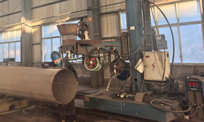
Des soudures impeccables sont le fruit de procédés maîtrisés, et non du hasard. Ce contrôle commence bien avant l'amorçage de l'arc.
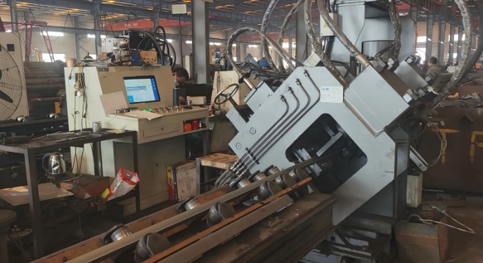
Spécification de procédure de soudage (WPS) et qualification : Chaque soudure sur une structure critique est régie par un DMOS qualifié. Ce document, validé par des essais physiques (Dossier de Qualification de Procédure – DQP), spécifie la « recette » exacte : nuances du métal de base et du métal d’apport, conception du joint (angles de chanfrein, épaisseur de la passe de fond), températures de préchauffage et entre passes, position de soudage, paramètres électriques (tension, intensité, vitesse de déplacement) et traitement thermique après soudage, le cas échéant. Ceci garantit des résultats reproductibles et prévisibles.
Préparation et ajustement critiques des articulations : Pour les soudures CJP, une préparation précise des bords par usinage ou découpe thermique de précision est essentielle. L'ajustement des pièces avant soudage doit être précis et uniforme ; des jeux excessifs contraignent le soudeur à déposer un excès de métal d'apport, augmentant ainsi le risque de défauts tels que des manques de fusion ou des déformations excessives.
Qualification de soudeur : Les soudeurs réalisant ces assemblages critiques doivent être certifiés selon le mode opératoire de soudage (WPS) spécifique utilisé, prouvant ainsi leur capacité à produire des soudures de qualité dans les conditions définies.
Même avec des procédures parfaites, des défauts humains ou liés au processus peuvent survenir. Les essais non destructifs (END) permettent d'inspecter la structure interne d'une soudure sans l'endommager. Pour les soudures des pylônes radar, le contrôle par ultrasons (UT) est la principale méthode d'examen volumétrique.
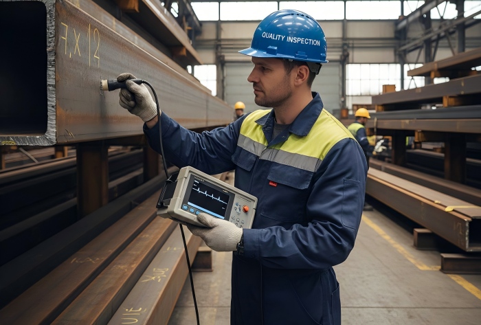
Les ultrasons excellent dans la détection de défauts internes et planaires qui sont critiques dans les scénarios de fatigue, tels que le manque de fusion, les fissures et les inclusions de laitier allongées.
Comment ça marche : Un technicien qualifié utilise un transducteur portatif qui génère des ondes sonores à haute fréquence (ultrasons). Ces ondes sont couplées à l'acier par l'intermédiaire d'un gel et se propagent à travers le matériau. Lorsqu'elles rencontrent une discontinuité (défaut), une partie de l'énergie sonore est réfléchie vers le transducteur. Le délai et l'amplitude de cet « écho » sont analysés afin de déterminer la profondeur, la taille et l'orientation du défaut.
Pourquoi l'UT pour les tours radar ?
Sensibilité aux défauts critiques : Les ultrasons sont exceptionnellement performants pour détecter les défauts plans, semblables à des fissures, qui sont les plus dangereux sous charge cyclique.
Dimensions de la profondeur : Il permet de déterminer avec précision la position et la taille d'un défaut à travers l'épaisseur, ce qui est crucial pour l'évaluation de la criticité en ingénierie.
Dossier permanent : Les unités UT numériques modernes fournissent des enregistrements de données A-scan et des données de position encodées, créant ainsi un enregistrement numérique vérifiable de la qualité de l'inspection.
Pour les articulations les plus critiques, Ultrason à réseau phasé (PAUT) Elle offre des capacités encore plus grandes. Au lieu d'un seul cristal piézoélectrique, la PAUT utilise une sonde multi-éléments où la synchronisation (phase) du déclenchement de chaque élément peut être contrôlée électroniquement.
Cela permet le pilotage et la focalisation électroniques du faisceau, permettant l'inspection de géométries complexes (comme les soudures de buses) à partir d'une seule position de sonde et offrant une caractérisation et une imagerie supérieures des défauts.
Il augmente la vitesse et la fiabilité de l'inspection, en générant des images C-scan ou S-scan détaillées qui donnent une image plus claire et plus intuitive de l'état interne de la soudure.
Bien que les ultrasons soient la méthode de référence pour les soudures primaires, un programme qualité rigoureux utilise une série de méthodes CND :
• Contrôle par magnétoscopie (MT) : Largement utilisée sur l'acier ferritique pour détecter les fissures de surface et subsurface (par exemple, au pied des soudures), cette méthode est rapide, fiable et indispensable pour repérer les signes de fatigue en surface.
• Test de ressuage (PT) : Utilisé pour les matériaux non ferromagnétiques ou comme alternative à la MT pour les défauts débouchants en surface.
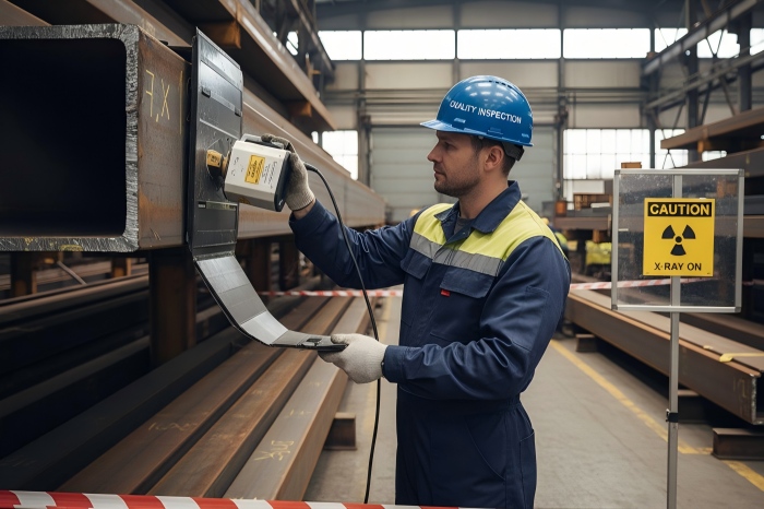
• Examen radiographique (RT) : Utilise les rayons X ou gamma pour créer une image, sous forme de film ou numérique, de la soudure. Excellente pour le contrôle volumétrique et la production d'une image 2D permanente en « ombre », elle est cependant généralement moins sensible que les ultrasons pour la détection de fissures fines et planes et présente d'importantes contraintes de sécurité et logistiques.
L'intégrité structurelle d'une tour de support radar est un engagement pris au bureau d'études et tenu en atelier. Cet engagement repose sur la qualité de ses assemblages soudés. En imposant des soudures à pleine pénétration pour les joints critiques, en garantissant leur mise en œuvre par des spécifications de procédures de soudage qualifiées et en vérifiant rigoureusement leur intégrité grâce à des contrôles ultrasoniques de pointe, les ingénieurs transforment l'acier brut en un élément fiable et durable.
Cette approche intégrée, à la croisée de la métallurgie, du génie mécanique et de la science des matériaux, garantit que la tour ne se contentera pas de tenir debout, mais qu'elle fonctionnera avec une stabilité à toute épreuve durant toute sa durée de vie, assurant fidèlement le fonctionnement du radar qu'elle supporte. Dans le domaine des infrastructures critiques, rien ne remplace ce niveau d'intégrité éprouvée.
Pour en savoir plus, consultez www.alttower.com


 Réseau IPv6 pris en charge