
 English
 русский
 español
 العربية
Recherche
Qu\'est-ce que tu cherches?
Recherche

L'alignement des trous de boulons est le paramètre de qualité le plus critique dans la fabrication des pylônes en acier à cornières. Un pylône en treillis autoportant est assemblé à partir de centaines, voire de milliers de cornières et de plaques de liaison à l'aide de boulons — et tout écart dans un seul trou de connexion peut rendre le montage sur site impossible. La tolérance standard de l'industrie pour la position des trous est de ±0,5 mm selon GB/T 2694, obtenue grâce à des systèmes de poinçonnage et de perçage à commande CNC qui éliminent les erreurs de mesure manuelle. La vérification finale est un assemblage d'essai, au cours duquel chaque trou de boulon doit réussir un test de passage de boulon à 100 % — l'alésage ou l'enfoncement forcé étant strictement interdits. Lorsqu'elle est exécutée correctement, cette précision garantit que des milliers de trous de boulons s'alignent parfaitement sur site, permettant un montage rapide et sans difficulté.
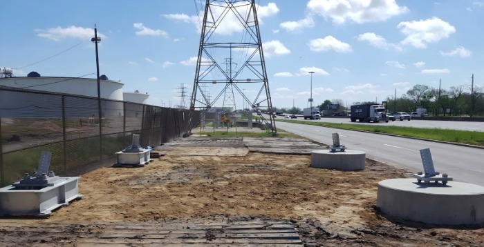
La précision de réalisation des trous est déterminante :Les assemblages boulonnés sont la principale méthode d'assemblage des pylônes en treillis, ce qui fait de la précision de la position des trous la base d'un montage réussi sur le terrain
La technologie CNC élimine les erreurs humaines :Les systèmes de poinçonnage et de perçage CNC sont pilotés directement par les données du logiciel de traçage, éliminant les mesures et le marquage manuels
Les tolérances se mesurent en demi-millimètres :Les normes industrielles comme GB/T 2694 exigent des tolérances d'espacement des trous et de distance au bord de ±0,5 mm
L'assemblage d'essai est indispensable :L'assemblage d'essai avant livraison vérifie un passage de boulons à 100 % — l'alésage ou l'enfoncement forcé sont strictement interdits
Un mauvais alignement entraîne des conséquences en cascade :Même de petits écarts peuvent s'accumuler sur des centaines de connexions, rendant les modifications sur site coûteuses et compromettant l'intégrité structurelle
Perçage ou poinçonnage :Le poinçonnage est efficace pour les cornières standard ; le perçage est nécessaire pour les sections épaisses (généralement >14 mm) ou les trous de grand diamètre afin de garantir la régularité de la paroi des trous
Qui recherche ces informations ?
| Type d'utilisateur | Intention principale | Principales préoccupations |
|---|---|---|
| Responsables des achats / Propriétaires de projets | Évaluer la capacité de fabrication des fournisseurs | Savoir si le fournisseur peut livrer des composants qui s'assemblent sur site sans reprise |
| Superviseurs du montage sur site | Résoudre les problèmes d'assemblage sur le terrain | Comment gérer les trous mal alignés, quelles en sont les causes et comment les éviter |
| Ingénieurs assurance qualité | Comprendre les normes industrielles et les meilleures pratiques | Tolérances acceptables, méthodes d'inspection et points de contrôle qualité |
| Fabricants de pylônes | Améliorer les processus de fabrication | Programmation CNC, méthodes de réalisation des trous et procédures d'assemblage d'essai |
| Ingénieurs de conception | Définir les tolérances et les détails des connexions | Comment les décisions de conception influencent la fabricabilité et l'assemblage sur site |
Résumé de l'intention de recherche :Les utilisateurs recherchent des informations faisant autorité sur la manière dont l'alignement des trous de boulons est obtenu et vérifié dans la fabrication des pylônes. Les responsables des achats veulent savoir ce qu'il faut rechercher chez un fournisseur ; les superviseurs de site ont besoin de solutions aux problèmes sur le terrain ; et les ingénieurs ont besoin de spécifications techniques pour soutenir les décisions de conception et de qualité. La préoccupation commune à tous les types d'utilisateurs est d'éviter les reprises coûteuses sur site et les retards de projet.
1. Quelle est la tolérance acceptable pour la position des trous de boulons ? Quelles normes s'appliquent ?
2. Quelle est la différence entre le poinçonnage et le perçage ? Quand chaque méthode est-elle utilisée ?
3. Comment la technologie CNC améliore-t-elle la précision de l'alignement des trous ? Les méthodes manuelles peuvent-elles atteindre la même précision ?
4. Qu'est-ce que l'assemblage d'essai ? Est-il requis pour chaque projet ? Que permet-il de vérifier ?
5. Que se passe-t-il lorsque les trous ne sont pas alignés sur site ? Peuvent-ils être alésés ou agrandis ? Quelles sont les conséquences structurelles ?
6. Comment le mauvais alignement des trous affecte-t-il l'intégrité structurelle ? Compromet-il la capacité de charge de la tour ?
7. Quels points de contrôle qualité dois-je attendre d'un fabricant reconnu ?
8. Comment puis-je vérifier la capacité d'un fournisseur en matière de réalisation des trous avant de passer une commande ?
9. Quelles sont les causes courantes du mauvais alignement des trous ? Une mauvaise programmation CNC ? Une déformation du matériau ? Une déformation due au soudage ?
10. Quels documents un fabricant doit-il fournir pour prouver la qualité de l'alignement des trous ?
Pourquoi l'alignement des trous de boulons est important et comment il affecte l'ensemble du cycle de vie du projet.
Comparaison technique des deux principales méthodes, avec critères de sélection.
Comment la commande numérique par ordinateur élimine les erreurs humaines et permet d'obtenir des tolérances de ±0,5 mm.
Présentation de GB/T 2694, TIA-222 et d'autres normes pertinentes.
Pourquoi l'assemblage d'essai avant livraison est le point de contrôle qualité irremplaçable.
Ce qui se passe lorsque les trous ne sont pas alignés — et pourquoi l'alésage est une solution de dernier recours.
Résumé des points d'inspection tout au long du processus de fabrication.
Capacités de l'entreprise et approche du contrôle qualité.
Réponses aux questions les plus courantes sur l'alignement des trous de boulons.
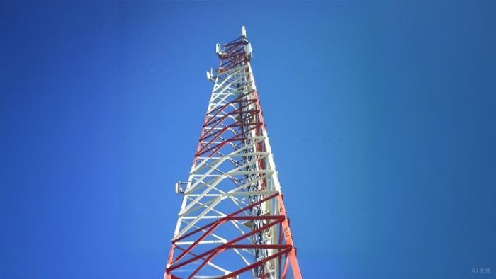
Une tour autoportante en acier cornière n'est pas un monolithe soudé — il s'agit d'une structure en treillis spatial assemblée à partir de centaines, voire de milliers, de cornières et de plaques de connexion à l'aide de boulons. Cette philosophie de construction boulonnée rend les tours en treillis transportables, modulaires et assemblables sur site. Mais cela signifie également que chaque trou de connexion doit être positionné avec précision — car si même un seul trou est décalé de quelques millimètres, tout le processus d'assemblage peut être bloqué.
Le défi est amplifié par l'échelle. Une tour de transmission ou de télécommunication typique peut comporter des milliers de trous de boulons, chacun percé ou poinçonné dans un composant différent. Ces composants sont fabriqués séparément, expédiés séparément et ne se rencontrent pour la première fois que sur le site de montage. Si les trous ne sont pas alignés, la tour ne peut pas être érigée.
C'est pourquoi la précision de réalisation des trous est déterminante pour un montage fluide sur site. Il s'agit du paramètre de qualité le plus critique dans la fabrication des tours — et de celui qui distingue les fabricants fiables de ceux qui provoquent des problèmes coûteux sur le chantier.
Il existe deux méthodes principales pour créer des trous de boulons dans les tours en acier cornière : le poinçonnage et le perçage. Chacune présente ses avantages et ses applications appropriées.
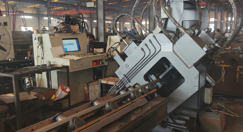
Pour la plupart des cornières en acier de dimensions standard, les fabricants utilisent des lignes de production CNC pour cornières afin de réaliser le poinçonnage. Cet équipement automatisé intègre l'alimentation, le convoyage, le poinçonnage et le cisaillage dans un seul processus continu.
Principaux avantages du poinçonnage :
Haute efficacité : idéal pour la production en volume de composants standard
Excellente uniformité : chaque composant est identique, éliminant les erreurs d'assemblage
Fonctionnement automatisé : piloté directement par les données du logiciel de traçage, éliminant les mesures et le marquage manuels
La presse à poinçonner crée avec précision des trous de boulons sur la surface de pied désignée et aux positions spécifiées conformément au programme, avec des tolérances d'espacement des trous et de distance au bord strictement contrôlées dans les limites des normes.
Limitation :Le poinçonnage ne convient pas à toutes les applications. Aucun trou ne doit être poinçonné lorsque l'épaisseur des matériaux dépasse le diamètre fini du trou.
Pour les cornières de grande épaisseur (généralement avec une épaisseur de pied supérieure à 14 mm) ou les trous de grand diamètre dépassant la capacité de poinçonnage, les fabricants passent au perçage.
Principaux avantages du perçage :
Qualité supérieure de la paroi des trous :Le perçage est un procédé de coupe qui produitaucun effet de déchirure par impact sur le métal de basece qui permet d'obtenir une plus grande régularité de surface sur les parois des trous et une meilleure cohérence du diamètre des trous
Adapté à l'acier haute résistance :Particulièrement important pour les composants de tours UHV et les nuances d'acier haute résistance
Traite les grandes sections :Les machines de perçage CNC multi-broches et les machines de perçage de type portique traitent efficacement le perçage de plusieurs trous sur de grandes cornières en acier et des plaques de connexion en une seule installation
Importation des données :Les données de perçage sont également importées automatiquement depuis le logiciel de dépliage, éliminant les erreurs manuelles.
| Facteur | Poinçonnage | Perçage |
|---|---|---|
| Épaisseur du matériau | ≤14 mm typiquement | >14 mm |
| Volume de production | Composants standard à grand volume de production | Composants à faible volume de production ou personnalisés |
| Qualité des trous | Bonne | Supérieure (parois plus lisses, aucune déchirure par impact) |
| Efficacité | Plus élevée | Plus faible |
| Idéal pour | Cornières standard, production en volume | Sections épaisses, acier haute résistance, composants UHV |
La transition des méthodes manuelles vers la fabrication de trous par CNC représente une amélioration fondamentale de la précision et de la fiabilité.
Méthodes manuellesreposaient sur des gabarits, des marques de traçage et les compétences de l'opérateur. Des erreurs pouvaient apparaître à travers :
Positionnement incorrect du gabarit
Mesures mal interprétées
Accumulation cumulative des tolérances
Erreurs induites par la fatigue lors d'opérations répétitives
Les systèmes CNC éliminent ces sources d'erreur. Les machines sont pilotées directement par les données générées par le logiciel de traçage. Cela signifie :
Aucune mesure ou aucun marquage manuel n'est requis
Chaque composant est produit selon des spécifications identiques
Les positions des trous sont précises à moins de ±0,5 mm selon GB/T 2694
Les données de production peuvent être stockées et réutilisées pour de futures commandes
Après le poinçonnage, les ouvriers ébavurent les bords des trous afin d'éviter d'endommager le revêtement galvanisé des boulons. Cette étape apparemment mineure est essentielle : des bords tranchants peuvent enlever le zinc des filets des boulons lors de l'installation, compromettant ainsi la protection contre la corrosion.
Plusieurs normes régissent les tolérances des trous de boulons dans la fabrication des pylônes.
GB/T 2694-2018 est la spécification actuelle pour la fabrication des pylônes de lignes de transmission. Elle exige :
Des tolérances d'espacement des trous et de distance au bord dans une limite de ±0,5 mm
Une vérification à 100 % du passage des boulons lors de l'assemblage d'essai
TIA-222-H spécifie les exigences pour les structures supportant des antennes. Les tolérances des trous comprennent :
Les trous percés doivent être 1/16 pouce (2 mm) plus grands que le diamètre nominal du boulon
Une mauvaise correspondance des trous entraînera un rejet
Les trous alésés doivent être cylindriques et perpendiculaires à l'élément
ISO 898-1/-2 : Propriétés mécaniques des boulons et des écrous
AWS D1.1 : Normes de soudage pour l'acier de construction
ASTM A123 : Spécifications de galvanisation à chaud
Remarque importante : Le diamètre du trou de boulon est généralement supérieur de 1/16 pouce (1,6 mm) au diamètre nominal du boulon. Ce jeu permet des ajustements mineurs lors de l'assemblage, mais introduit également un glissement des boulons lorsque le pylône est soumis à une charge, ce qui modifie sa réponse en déplacement. C'est pourquoi la précision du positionnement des trous est essentielle : un jeu excessif ou un mauvais alignement aggrave le problème.
L'assemblage d'essai est une étape irremplaçable de vérification de la qualité dans la fabrication des pylônes et le dernier point de contrôle technique. C'est à ce moment que le fabricant assume l'entière responsabilité de la qualité de la livraison.
Conformément à GB/T 2694 et aux exigences du contrat du projet, des sections représentatives de pylônes ou des têtes et nœuds de corps de pylône complets sont sélectionnés dans chaque lot de production pour un préassemblage en usine.
L’assemblage d’essai est réalisé sur une plateforme d’assemblage dédiée, mise à niveau avec précision afin de simuler le plan de référence d’installation réel. Les ouvriers suivent strictement les plans de montage et les listes de boulons, en utilisant des boulons et des rondelles identiques à ceux utilisés sur site.
Pendant l’assemblage d’essai, les ingénieurs qualité se concentrent sur trois domaines critiques :
Écarts géométriques globaux : Largeur du corps du pylône, différences diagonales et différences de niveau des bras transversaux
Ajustement des joints de connexion : Vérification que le nettoyage des racines, le rabotage arrière et les résultats du cintrage à chaud répondent aux normes
Taux de passage des boulons de 100 % : L’alésage ou l’enfoncement forcé sont strictement interdits
Les composants accessoires tels que les échelles, les plateformes et les supports de câbles sont également vérifiés pour leur compatibilité de connexion.
Après l’assemblage, des télémètres laser, des théodolites et des outils de mesure spécialisés sont utilisés pour effectuer des mesures complètes, enregistrer chaque point de données et prendre des relevés photographiques.
Si un écart est constaté, l’équipe remonte immédiatement jusqu’au procédé responsable et met en œuvre des actions correctives jusqu’à ce que toutes les exigences de tolérance de conception soient pleinement respectées.
Une fois l’assemblage d’essai validé, les composants sont numérotés selon la séquence de montage, démontés et emballés pour la livraison.
Cette étape élimine fondamentalement les incertitudes liées au montage sur site. En particulier pour les projets d’exportation, l’identification et la résolution des problèmes au niveau national garantissent que les pylônes arrivent sur site prêts pour un montage fluide et efficace.
L’assemblage doit être réalisé sans effort exceptionnel pour aligner les trous de boulons ou forcer les pièces en position. Les trous de boulons ne doivent pas être alésés ni agrandis. Il ne s’agit pas seulement d’une bonne pratique, mais d’une exigence contractuelle dans la plupart des spécifications.
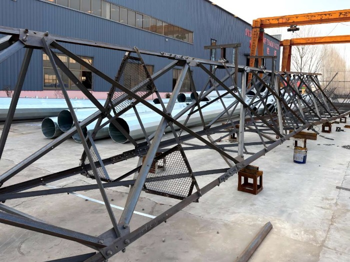
Malgré les meilleurs efforts lors de la fabrication, des problèmes d’assemblage sur site peuvent toujours survenir. Il est essentiel de comprendre les causes et les conséquences.
Chaîne de petits écarts dimensionnels : Un écart de 2 mm à 4 mm dans la longueur des pieds peut déplacer suffisamment les positions des trous pour créer des travaux de modification sur site
Déformation due au soudage : L’acier des pieds du pylône peut se déformer pendant le soudage, provoquant un décalage des trous
Technologie de poinçonnage inappropriée : Des fissures peuvent se former au bord des trous de boulons si les paramètres de poinçonnage sont incorrects
Dommages liés au transport : Les composants peuvent être pliés ou déformés pendant l’expédition
Lorsque les trous ne sont pas alignés sur site, les entrepreneurs peuvent être tentés d’aléser ou d’agrandir les trous pour insérer les boulons. Cependant, cette pratique entraîne des conséquences structurelles importantes :
Le glissement des boulons entraîne une augmentation significative de la force exercée sur certaines barres connectées
Lorsque le jeu des boulons est inférieur à 2 mm, la variation du jeu des boulons a l’effet le plus significatif sur l’effort axial des barres
L’intégrité structurelle est compromise : la connexion ne se comporte plus comme prévu dans la conception
Les performances à long terme sont affectées : l’augmentation du glissement des boulons modifie la réponse en déplacement du pylône sous charge
Directives pour les modifications sur site : Si l’alésage est absolument nécessaire, n’alésez pas plus de 5 % des trous d’une connexion. Cependant, l’approche privilégiée consiste à prévenir entièrement le problème grâce à un contrôle qualité rigoureux de la fabrication et à un assemblage d’essai.
| Étape | Opérations principales | Points de contrôle qualité clés |
|---|---|---|
| Préparation des matériaux | Réception et découpe des matériaux | Certificats du laminoir, précision dimensionnelle |
| Poinçonnage CNC | Poinçonnage automatisé des trous | Précision de positionnement des trous (±0,5 mm), ébavurage |
| Perçage CNC | Perçage des trous pour les sections épaisses | Lissage des parois des trous, uniformité des diamètres |
| Formage | Cintrage à froid/à chaud | Stabilité dimensionnelle, intégrité de surface |
| Assemblage d'essai | Assemblage complet ou représentatif | Passage des boulons à 100 %, écarts géométriques |
| Emballage | Numérotation, emballage, mise en caisse | Identification des composants, protection du revêtement |
Qingdao Altai Tower Co., Ltd. est un fabricant professionnel de tours de télécommunication, de pylônes électriques et d'accessoires pour tours, établi en 2003. L'entreprise est spécialisée dans la conception, la fabrication et l'installation de tours en acier, avec des produits exportés vers plus de 100 pays et régions.
| Capacité | Spécification |
|---|---|
| Capacité de production | 3 000 tonnes métriques par mois |
| Galvanisation | Atelier interne équipé de matériel italien, respectant strictement la norme ASTM A123 |
| Délai de production | 30 jours après paiement |
| Certifications | ISO 9001, ISO 14001, ISO 45001, CE |
| Brevets | 23 brevets internationaux |

Qingdao Altai Tower a intégré la vérification de la qualité tout au long du processus de fabrication plutôt que de la limiter à un contrôle final. Cette approche permet d'identifier les problèmes potentiels à un stade précoce, d'éviter les retards liés aux reprises tout en garantissant une production constante conforme aux normes spécifiées.
Technologie CNC est la base de la précision de fabrication des trous de l'entreprise. Les machines CNC utilisent des vérins hydrauliques et des matrices personnalisées pour poinçonner le modèle exact de trous destiné aux boulons avec une vitesse et une précision remarquables. La technologie CNC garantit que chaque composant est identique, éliminant les erreurs d'assemblage et assurant l'intégrité structurelle.
Assemblage d'essaiest effectué sur chaque lot de production, avec une exigence de taux de passage des boulons de 100 %. Si un quelconque écart est détecté, l'équipe remonte immédiatement jusqu'au processus responsable et met en œuvre des actions correctives jusqu'à ce que toutes les exigences de tolérance de conception soient pleinement respectées.
Atelier de galvanisation interne équipé de matériel italien, garantissant une qualité de revêtement constante
Certifications complètes : ISO9001, ISO14001, ISO45001
23 brevets internationaux démontrant une innovation en ingénierie
Conception modulaire permettant un emballage efficace et un déploiement rapide
Assemblages boulonnés — aucune soudure sur site requise, simplifiant l'installation
Traçabilité complète : chaque composant est suivi tout au long du flux de production
| Paramètre | Poinçonnage/perçage CNC | Méthodes manuelles/gabarits |
|---|---|---|
| Précision de la position des trous | ±0,5 mm (GB/T 2694) | ±2 mm ou plus |
| Cohérence | Chaque composant est identique | Variable — dépend de l'opérateur |
| Sources d'erreur | Minimales — automatisées | Multiples — mesure, marquage, usure du gabarit |
| Vitesse de production | Élevée | Faible |
| Intégration des données | Directement depuis le logiciel de traçage | Saisie manuelle des données |
| Taux de reprise | Faible | Élevé |
| Adaptabilité aux motifs complexes | Excellente | Limitée |
| Réussite de l'assemblage sur site | Prévisible | Imprévisible |
R : Selon GB/T 2694, les tolérances d'espacement des trous et de distance au bord doivent être comprises dans ±0,5 mm. Cela s'applique aux opérations de poinçonnage et de perçage.
R : Le poinçonnage utilise un vérin hydraulique et une matrice pour découper le trou, adapté aux cornières standard jusqu'à une épaisseur de 14 mm. Le perçage est un procédé de coupe utilisé pour les sections plus épaisses (>14 mm) ou les trous de grand diamètre, produisant des parois de trous plus lisses sans déchirure due à l'impact.
R : Une tour en treillis est assemblée à partir de centaines, voire de milliers de connexions boulonnées. Tout écart au niveau d'un seul trou de connexion peut rendre le montage sur site impossible. L'assemblage d'essai vérifie que chaque trou de boulon est parfaitement aligné avant l'expédition des composants.
R : L'alésage ou l'enfoncement forcé est strictement interdit dans la pratique professionnelle. L'assemblage doit être réalisé sans effort extraordinaire pour aligner les trous de boulons. Si un alésage est absolument nécessaire, il ne faut pas aléser plus de 5 % des trous d'une connexion.
R : Un mauvais alignement entraîne un glissement des boulons, ce qui augmente la force exercée sur les barres connectées et compromet l'intégrité structurelle. Les modifications sur site sont coûteuses, chronophages et peuvent annuler les garanties.
R : Les systèmes CNC sont pilotés directement par les données du logiciel de développement, éliminant les erreurs de mesure et de marquage manuels. Ils atteignent une précision de ±0,5 mm et garantissent que chaque composant est identique.
R : Un fabricant réputé doit fournir des certificats de laminage, des données de production CNC, des rapports d'assemblage d'essai avec preuves photographiques, des rapports de mesure (données de télémètre laser et de théodolite) ainsi que des relevés de vérification du passage des boulons.
R : Les trous de boulons sont généralement 1/16 pouce (1,6 mm) plus grands que le diamètre nominal du boulon afin de permettre l'assemblage. Cependant, ce jeu introduit un glissement des boulons lorsque la tour est chargée, modifiant sa réponse en déplacement. La précision du positionnement des trous minimise cet effet.
R : Le poinçonnage convient généralement aux cornières jusqu'à une épaisseur de 14 mm. Le perçage est nécessaire pour les sections plus épaisses ou lorsque le diamètre du trou dépasse la capacité de poinçonnage.
R : Demandez les rapports d'assemblage d'essai, les certificats d'étalonnage CNC, les rapports d'inspection indiquant les mesures de position des trous et, si possible, visitez l'usine pour observer les processus de poinçonnage/perçage et d'assemblage d'essai.
L'alignement des trous de boulons n'est pas un détail mineur dans la fabrication des tours : il constitue la base sur laquelle repose un assemblage réussi sur site. Une tour avec des trous parfaitement alignés est montée facilement, dans les délais et dans le respect du budget. Une tour avec des trous mal alignés devient un cauchemar de reprises, de retards et d'intégrité structurelle compromise.
La voie vers un alignement parfait est clairement définie : poinçonnage et perçage contrôlés par CNC atteignant des tolérances de ±0,5 mm selon GB/T 2694, suivis d'un assemblage d'essai rigoureux vérifiant le passage de 100 % des boulons. Lorsqu'un fabricant suit ce processus, la tour qui s'assemble sur le plancher de l'usine s'assemblera également sur le terrain.
Le choix est simple : investir dans la précision au stade de la fabrication ou payer pour des reprises au stade du montage. Une approche fournit des résultats prévisibles ; l'autre entraîne des coûts imprévisibles. Pour les maîtres d'ouvrage et les ingénieurs, la décision est claire : la précision de l'alignement des trous n'est pas négociable, c'est la condition préalable à la réussite du projet.
Prêt à garantir que votre projet de tour évite les problèmes coûteux d'assemblage sur site ? Contactez aujourd'hui l'équipe d'ingénierie de Qingdao Altai Tower pour discuter de vos exigences de qualité et de votre plan de fabrication sur mesure.



 Réseau IPv6 pris en charge