
 English
 русский
 español
 العربية
Recherche
Qu\'est-ce que tu cherches?
Recherche

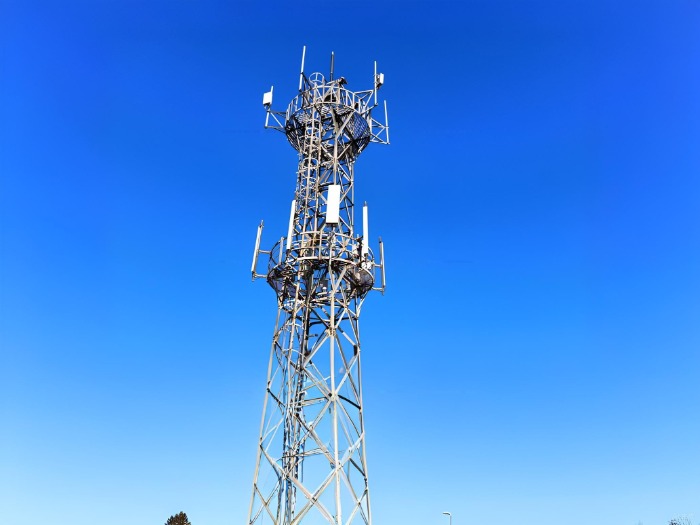
L'infrastructure des télécommunications qui alimente notre monde moderne repose sur des fondements de tours en treillis d'acier —dont beaucoup ont été construites il y a des décennies pour les réseaux 2G et 3G. Aujourd'hui, ces structures vieillissantes sont sollicitées pour supporter des équipements 5G et de générations futures bien plus lourds, souvent soumis à des contraintes accrues liées au vent et au gel, imposées par les normes de construction modernes.
La question qui se pose aux opérateurs de réseau n'est pas de savoir s'il faut remplacer ces pylônes, mais comment prolonger leur durée de vie de manière rentable. La réponse réside dans un ensemble de solutions éprouvées. techniques de renforcement structurel qui permet de restaurer, voire d'améliorer, la capacité des pylônes en cornière d'acier vieillissants avec un temps d'arrêt minimal.
De nombreuses tours de télécommunications actuellement en service ont été construites il y a plus de 20 ans, et certaines ont 40 à 50 ans, voire plus. À l'échelle mondiale, environ 20 % des infrastructures de tours de transmission et de communication ont plus de 40 ans. Ces structures sont confrontées à de multiples défis : dégradation des matériaux due à la corrosion et à la fatigue, tassement des fondations et, surtout, exigences accrues en matière de charges de conception, qui dépassent souvent leurs spécifications d'origine.
L'argument économique en faveur de la rénovation est convaincant. Le coût de construction d'une nouvelle tour – incluant l'acquisition du terrain, les permis, les travaux de fondation et l'érection – dépasse largement l'investissement nécessaire à un renforcement structurel ciblé. De plus, les tours conçues conformément aux normes ANSI/TIA-222 peuvent avoir une durée de vie illimitée si elles sont correctement entretenues et modernisées. Le défi consiste à identifier les stratégies de renforcement les plus efficaces.
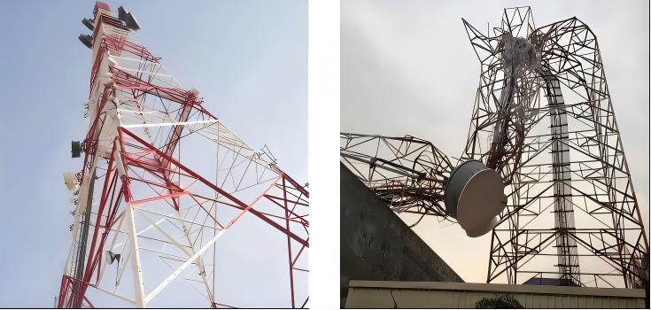
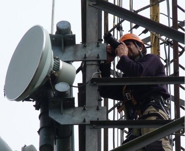
Avant tout travail de renforcement, une évaluation structurelle complète est obligatoire. La norme ANSI/TIA-222-H fournit des recommandations pour l'élaboration de programmes de maintenance et d'évaluation de l'état des ouvrages, en spécifiant des intervalles d'inspection de trois ans pour les mâts haubanés et de cinq ans pour les structures autoportantes. Une évaluation adéquate doit comprendre une analyse documentaire des plans de récolement et des dossiers de maintenance existants, suivie d'une inspection sur site par des ingénieurs en structure expérimentés. Ces derniers utilisent un système de notation de l'état des ouvrages (0-100) qui classe les structures selon leur niveau de risque : rouge (risque élevé, intervention urgente), orange (risque moyen, mesures correctives) et vert (risque faible, surveillance préventive).
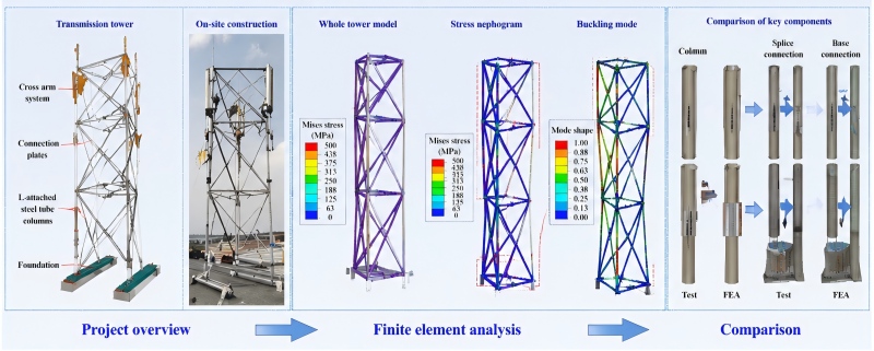
L'analyse par éléments finis (AEF) est essentielle pour quantifier la capacité de réserve. Des études indiquent que 30 à 40 % des pylônes anciens dépassent les limites de contrainte admissibles selon les normes actuelles. L'analyse doit s'attacher à identifier les éléments pouvant être renforcés avec le plus grand avantage structurel, en accordant une attention particulière aux conditions de charge du vent et du givre. Une caractérisation erronée de la distribution du vent spécifique au site constitue le principal facteur de risque de défaillance des pylônes, la corrosion venant juste après.
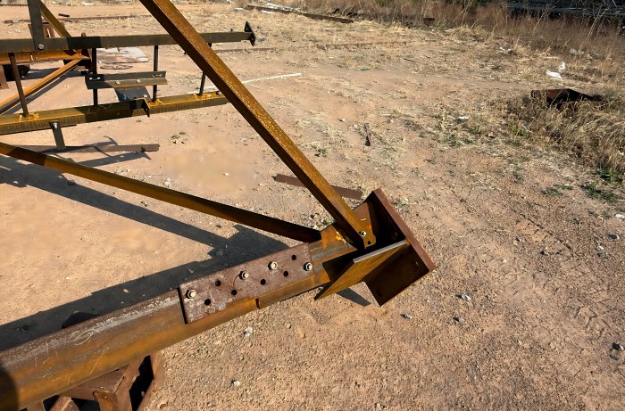
La méthode la plus courante pour renforcer les pieds de pylônes consiste à fixer des cornières supplémentaires parallèlement aux pieds existants à l'aide d'assemblages boulonnés. Cette approche a été largement validée par des recherches expérimentales. Des études démontrent qu'il est possible d'accroître la capacité portante de 50 à 100 % selon le nombre, le type et l'emplacement des connecteurs. Les éléments de renforcement répartissent la charge avec les pieds existants grâce à des systèmes d'assemblages boulonnés, et, point important, la précontrainte n'influence pas significativement la résistance ultime de l'ensemble de la structure. Pour des résultats optimaux, le renforcement doit s'étendre au-delà du point de premier besoin afin de compenser le décalage de transfert de charge.
Pour les pylônes élancés, l'ajout de plusieurs contreventements horizontaux (diaphragmes) à mi-hauteur permet de réduire significativement l'élancement effectif et d'éviter le flambement prématuré. Cette méthode est particulièrement efficace pour les pylônes très élancés, où la rupture est due au flambement plutôt qu'à la résistance à l'écrasement. Des études ont démontré qu'une amélioration considérable de la résistance à la compression peut être obtenue grâce à cette approche.
Les assemblages boulonnés des pylônes vieillissants constituent souvent le maillon faible de la structure. Une méthode de renforcement non destructive, utilisant des éléments supplémentaires fixés par de nouveaux boulons à haute résistance, a été mise au point et testée. Parmi les paramètres de conception critiques figure la distance entre les joints, c'est-à-dire l'espacement entre le nouveau boulon et les trous de boulons existants. Les résultats expérimentaux indiquent que cette distance doit être au moins 1,5 fois supérieure à la largeur de la section transversale de l'équerre pour optimiser la résistance ultime. Cette distance modifie le mode de rupture prévu, permettant ainsi à l'assemblage renforcé d'atteindre sa résistance maximale.
Le polymère renforcé de fibres de carbone (PRFC) s'est imposé comme une technologie révolutionnaire pour le renforcement des pylônes, offrant une résistance élevée et une grande légèreté sans augmentation notable du poids de la structure ni modification significative de sa forme. L'application du PRFC consiste à coller des feuilles multicouches sur la surface de l'acier à l'aide d'adhésifs spécifiques ; ce procédé, simple et pratique, n'endommage pas les cornières d'origine.
La recherche démontre que l'utilisation quatre couches de CFRP d'une épaisseur totale de 0,668 mm Ce matériau peut répondre à la plupart des exigences de renforcement des cornières. Pour une efficacité de renforcement maximale, les couches de PRFC doivent être posées avec toutes les plis orientés à 0° dans le sens de la compression axiale. D'un point de vue économique et de performance, une configuration à « enveloppement partiel » – recouvrant la partie centrale de l'élément plutôt qu'un enveloppement complet – offre le meilleur compromis entre efficacité de renforcement et coût des matériaux.
Une étude récente portant sur un poteau de tour de télécommunications à treillis fissuré et renforcé par des matériaux composites à fibres de carbone (CFRP) a montré que la charge limite d'élasticité augmentait de 5,2 % et la rigidité limite d'élasticité de 11,5 % par rapport au poteau d'origine non fissuré. Plus impressionnant encore, la contrainte au bord de la fissure diminuait de 229,1 MPa (73,3 %) après renforcement, la zone de concentration des contraintes étant transférée de la fissure vers l'ancrage. Dans les conditions de charge les plus défavorables, le déplacement maximal diminuait de 7,422 mm (29,1 %) et le rapport de contrainte de 1,092, confirmant ainsi l'efficacité des CFRP pour l'amélioration de la charge et la redistribution des contraintes.
En cas de dommages localisés ou de concentrations de contraintes excessives, le remplacement ciblé d'éléments par de l'acier à haute résistance est une solution essentielle parmi les mesures de renforcement. Des études indiquent que le remplacement par de l'acier à haute résistance, combiné à un enrobage en PRFC et à la rénovation des fondations, peut améliorer la capacité portante de 25 à 50 %.
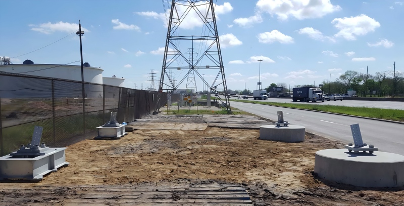
Le tassement du socle et l'instabilité des fondations constituent des modes de défaillance critiques, responsables souvent d'une réduction de stabilité de 15 à 25 % pour les tours anciennes. Les techniques de consolidation des fondations comprennent le renforcement par sous-œuvre, l'injection de coulis et l'ajout de colliers en béton armé autour des semelles existantes. Tout renforcement de la superstructure doit s'accompagner d'une vérification de la capacité portante des fondations afin de garantir que l'ensemble du système puisse supporter les charges accrues en toute sécurité.
Le renforcement des pylônes vieillissants n'est pas une solution ponctuelle, mais une stratégie de gestion continue de leur cycle de vie. Les pylônes en service depuis près de 30 ans peuvent voir leur durée de vie prolongée de plusieurs années grâce à des programmes d'inspection et de maintenance ciblés. Le remplacement des éléments en acier à haute résistance et le renforcement par des matériaux composites à fibres de carbone (CFRP) peuvent prolonger leur durée de vie de 20 à 30 ans au-delà de la durée de vie initialement prévue, ce qui peut potentiellement porter leur durée de vie totale à plus de 50 ans. Une approche systématique génère des avantages économiques qui vont au-delà des économies directes réalisées sur les nouvelles constructions, comme le démontrent des études de cas concluantes montrant une réduction des risques pouvant atteindre 40 % grâce à un renforcement proactif.
La plupart des infrastructures de télécommunications existantes conservent une capacité structurelle importante. Une évaluation appropriée et un renforcement ciblé – par l’ajout d’éléments, le boulonnage haute résistance, l’enrobage en PRFC ou la rénovation des fondations – permettent de transformer un bâtiment vieillissant en un atout durable. Dans la course au déploiement de la 5G et des technologies suivantes, la modernisation n’est pas qu’une simple mesure d’économie ; c’est un impératif stratégique.
Pour en savoir plus, consultez www.alttower.com


 Réseau IPv6 pris en charge